A variety of methods and techniques are used for locating a buried utility line. Before deciding on a best approach for a specific line locating challenge, key decisions have to be made based on information at hand. During the planning phase of your locate challenge, information must be gathered from a visual inspection of the job site and available mapping data before choosing a locating technique. When the challenge is identified the next step is to choose a type of technology for the specific challenge.
An Electromagnetic (EM) Pipe and Cable Locator is the first choice for locating buried line that is conductive in nature and has a continuous pathway for signaling current to flow. This is the most common locating equipment and consists of a portable signal transmitter and a handheld signal receiver. The transmitter is used to apply current to the buried line and creates a detectable magnetic field called a signal. The receiving unit detects the signal and provides information about the signal field including horizontal centerline of the field, intensity of the field and estimated distance to the center of the signal. When looking for a nonmetallic pipe, EM devices will not work unless you first insert a metallic conductor into the pipe. This is called rodding.
Most conventional signal receivers can recognise two types of signals – active and passive. Active signals are the signals that you apply deliberately with your signal transmitter whereas passive signals are signals that are created by outside sources and may naturally be present on your buried line. Applying an active signal for locating in the conduction/ direct connection mode is our national CGA best practice. Passive signal locating method is primarily used to sweep an area for the presence of any lines carrying these types of signal. Passive signals are often present on many types of buried utilities so this method is not ideal for targeting one line at a time in a congested area.
There are 3 techniques for applying an active signal to an underground line with a transmitter: Direct Connection, Close Induction and Broadcast Induction.
1ST CHOICE – Direct Connection Technique:
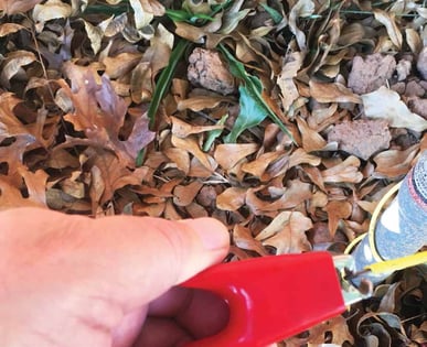
The first and best choice for applying an EM signal should always be the direct connection technique when possible. This method provides a metal-to-metal contact between transmitter and targeted underground line and allows you to use a low frequency which is best for targeting a single utility in a congested area due to low levels of signal bleed off to other lines in the area. Direct connection is the process of connecting a direct lead from the transmitter to the target facility and connecting a ground lead from the transmitter to a temporary ground stake or other grounding source.
Advantage: A broader range of signal frequencies can be used including very low frequencies used for long distance locating with very little signal bleed over. Direct connection is a great technique for targeting one line at a time in a congested utility environment and the only practical way to locate a copper tracer wire buried with a plastic pipe.
Disadvantage: Direct connection requires a direct metal-to-metal access point to hook up the transmitter. In some cases these access point are limited and signal current may not travel as far as you need them to. Another disadvantage is common grounding connection between several types of buried lines provide signal currents a direct pathway from your target line to other lines bonded with your targeted line causing unwanted signals to appear on non-targeted lines which share the ground source. This is very common in cabling systems.
2ND CHOICE – Close Induction Technique:
If direct connection is not possible or does not give you the results you need, the use of an induction clamp (coupler) is the second most effective method of applying a locate signal onto the target line. This method limits the choices of broadcast frequency and power outputs when compared to direct connection. The close inductive coupler, commonly called the ring clamp, produces a strong EM signal field within the clamp which is transferred to the conductor encircled by the coupler clamp. The ring clamp windings are similar to the primary winding inside an electrical transformer. A conductor within the winding becomes a secondary circuit connected to the transmitter through the EM field transfer of energy. In many circumstances the close induction clamp is an available accessory that is either included in the kit or can be ordered separately.

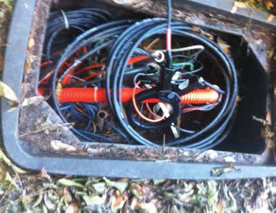
Advantage: The clamp can be applied without making metal-to-metal contact to the line. The clamp is ideally used for applying signals to cables. A signal is transferred from clamp to cable without taking the cable out of service in a pedestal, manhole, electrical panel or junction box. The clamp can be placed around conduits that have cables in them that line a conduit, are on a building wall or located on a pole.

Disadvantage: The ring clamp usually provides fewer low frequency broadcast choices for long distance locates. Another disadvantage to this technique is, like direct connection, common grounding of other cables can create multiple signals.
3RD CHOICE – Broadcast Induction Technique:
The least-preferred method is induction or broadcast technique. Broadcast induction is an indirect way to transfer a signal from the transmitter to a buried line. This technique in normally used as a last resort and can cause signals to appear on all conductive lines in an area.
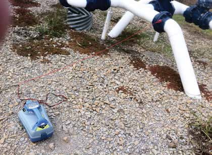
Broadcast induction is done by turning on the signal transmitter with no attachments plugged in. The majority of signal transmitters available today have a built-in inductive broadcast antenna that will normally activate simply by turning on the transmitter. There are a few models that require the user to press a specific button to activate the internal broadcast antenna. Consult your user’s guide for information on broadcast induction activation and transmitter positioning over a buried line.
Advantages: When done correctly, the inductive broadcast technique can place a signal on an underground line that does not have a nearby access point. This technique is a good way to attempt to send signal to a tracer wire that has been cut at several locations. This technique can also be deployed by two people when sweeping an area for conductive lines. To conduct a sweep, one person holds the receiver and the other person holds the transmitter as they walk in tandem. If they cross a buried line at same time, the person with the receiver will read a good signal.
Disadvantage: Higher frequencies are often necessary when inducing a signal. By nature, high frequency signals are prone to ghost signals and can easily bleed over to other lines in the ground. It can be very difficult to induce a signal field on a small tracer wire. Induced signal fields can flow on abandon lines as easily as live lines and is a poor way to single out a specific line in a congested utility easement. Similar to trying to target shoot with a shotgun, you’re likely to hit more than one target.
There are several golden rule for locators to follow. One of those rules are to direct connect whenever possible.
Bob Nighswonger is President/CEO of Utility Training Academy Inc. Bob has 30 years of line locating and damage prevention experience and has been a long time professional instructor of line locators. Bob can be reached for questions and feedback by emailing bob@utasearch.com.
Comments